








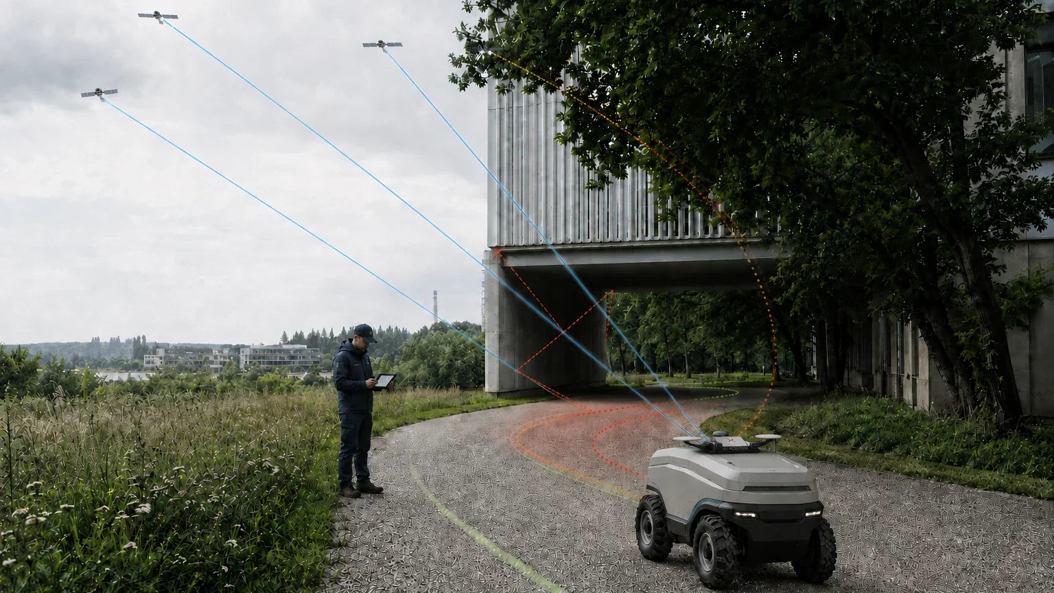
An INS buys you seconds. The question is whether seconds are enough.
Adding an IMU genuinely helps — it smooths the trajectory, provides attitude, and bridges short GNSS gaps. But inertial position error grows with the square of elapsed time, and published results for MEMS-grade inertial in real urban driving put the drift after a 60-second outage in the range of metres to tens of metres, not centimetres. An INS is a tool for seconds. If your robot is blocked for the length of a building, it is usually enough. If it works under canopy or between buildings for minutes at a time, it is not.
What an IMU actually contributes
An inertial measurement unit measures specific force and angular rate. Integrate angular rate once and you get attitude; integrate acceleration twice and you get position. That double integration is the whole story: any residual bias in the accelerometer, after gravity has been removed using an attitude estimate that is itself drifting, is integrated twice into position.
The practical consequences follow directly:
- Error accelerates. Doubling the outage length far more than doubles the position error.
- It drifts at standstill. Unlike odometry or vision, an inertial solution degrades even when the robot is not moving.
- It needs motion to stay healthy. Biases and heading are observable when the vehicle accelerates and turns. A slow, straight, stop-start duty cycle is close to the worst case for observability.
- Grade sets the timescale, and the price. Consumer, industrial, tactical and navigation-grade inertial sensors differ by orders of magnitude in drift and in cost. Moving up a grade extends the usable gap; it does not change the shape of the curve.
Two published results, and why they disagree
Search for evidence on this question and you will find numbers that appear to contradict each other by two orders of magnitude. They do not actually contradict each other, and understanding why is the most useful thing on this page — because the same trick is what makes a vendor's bridging specification look better than the system will behave on your machine.
Result one: ten centimetres after 30 seconds
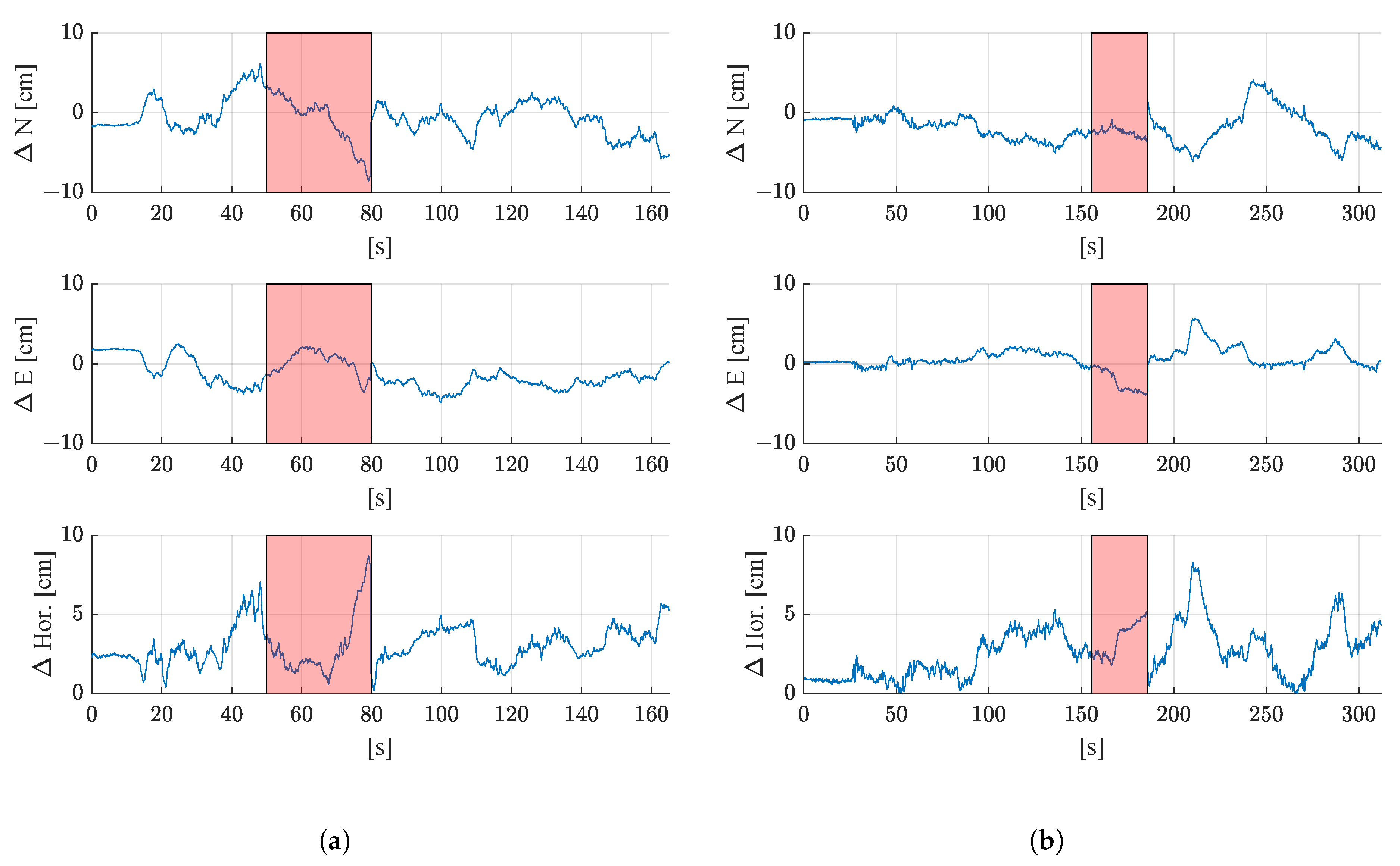
Impressive, until you read the conditions. The IMU is a mid-range MEMS unit — an Xsens MTi-G-710, the sort of module that sits in the low thousands of dollars, well above a bare MEMS chip and well below anything tactical. The vehicle is a tracked compost turner travelling at less than 1 km/h, so across the entire 30-second outage it covers under eight metres. Left and right wheel speeds and a tracked-vehicle slippage model are active throughout. And the outages are simulated in post-processing on data recorded while the satellites were actually visible.
What that result really demonstrates is that wheel odometry and a good dynamic model can hold a slow tracked vehicle over a short distance. It is close to silent on how far an IMU drifts.
Result two: metres, sometimes tens of metres
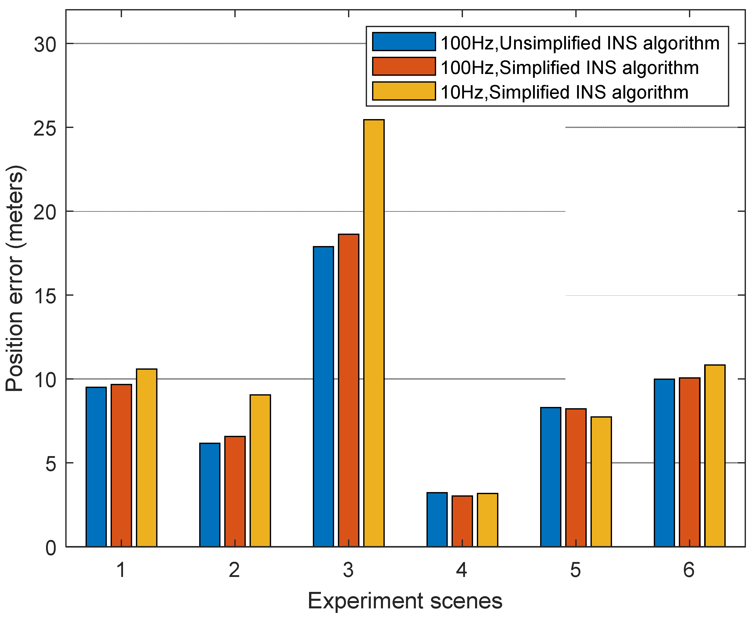
A road vehicle in real urban traffic, MEMS inertial, 60-second gaps: single-digit to low-tens-of-metres error, varying by a factor of eight between scenes with the same hardware. That variation is the point. The same sensor produced three metres in one place and twenty-five in another.
What actually determined the difference
Not the price of the IMU. Four things, none of which appear on a datasheet:
- Distance covered during the gap. Eight metres at walking pace versus a kilometre at road speed. Inertial error compounds with time, but everything aiding it degrades with distance.
- Whether wheel odometry was trustworthy. On tracks at 1 km/h across a compost windrow, with a slip model, it is excellent. On a skid-steer robot turning on wet grass, it is a source of error rather than a fix for one.
- Dynamics. Turns, accelerations and vibration keep inertial biases observable. A slow, straight crawl and a stop-start duty cycle are the hard case, not the easy one.
- Whether the outage was real. Discarding GNSS in post-processing gives you a clean environment either side of the gap. A real urban canyon degrades the satellites before, during and after — and often the aiding sensors with them.
How to read a bridging claim
When any supplier — including this one — shows you an outage figure, five questions decide what it is worth:
- How far did the vehicle travel during the outage, not how long did it last?
- Was wheel odometry active, and would it be trustworthy on your terrain and drivetrain?
- Was the outage real, or removed from data recorded in open sky?
- What grade of inertial sensor, and what does it cost against your bill of materials?
- Is the number a mean, or the worst case across scenes? The urban result above is a factor of eight apart on identical hardware.
Applied to your own machine, those questions usually collapse into one: for a robot working at a few kilometres an hour in an environment that removes GNSS for minutes at a time, the honest planning number is metres, not centimetres.
The part nobody mentions: an INS has to converge first
Inertial biases are not known in advance. They have to be estimated, and they are only observable when the filter has something trustworthy to compare against. In Fixposition's own system that means bias convergence requires a maintained RTK-fixed GNSS lock, motion that excites the IMU in all axes rather than a straight slow crawl, a base station within about 15 km, and an environment without many reflective surfaces. Electrically noisy neighbours matter too — USB3 devices and unshielded cables near a GNSS antenna are a documented cause of trouble.
Read that list again, because it inverts the usual assumption. An inertial solution needs a good GNSS environment in order to become ready to carry you through a bad one. A robot commissioned entirely inside an orchard or a courtyard may never converge properly in the first place. Plan a convergence run in open sky as part of your commissioning procedure, not as an afterthought.
Where wheel odometry helps, and where it does not
Adding wheel ticks is the standard next step and it is worthwhile. Fixposition treats wheel speed as a fourth sensor in the fusion engine, and cites two specific gains: higher accuracy during outages, and better detection of when the vehicle is genuinely stationary. Input can arrive over UART, TCP or CAN in Fixposition's measurement format, over standard vehicle CAN/OBD2, or through the ROS driver as a Twist or Odometry message, in single-point, two-wheel or four-wheel configurations.
Two honest limits. Wheel slip on wet grass, loose soil or gravel injects error directly, skid-steer platforms violate the kinematic assumptions during turns, tyre radius changes with load and wear, and odometry says nothing about lateral drift. And although wheel speed improves positioning, it does not help the IMU biases converge — that still depends on RTK-fixed GNSS and proper excitation.
Why a camera changes the arithmetic
Visual odometry estimates motion by tracking features in the scene across frames. Its error properties are fundamentally different from inertial:
| Inertial only | Vision-inertial | |
|---|---|---|
| Error grows with | Elapsed time, quadratically | Distance travelled |
| At standstill | Continues to diverge | Holds position |
| Best conditions | Short, dynamic manoeuvres | Textured scenes, moderate speed |
| Worst conditions | Long, slow, low-dynamic operation | Featureless scenes, poor lighting, motion blur |
Those failure modes are close to complementary, which is why the two are fused rather than chosen between. Vision supplies the long-timescale stability that inertial lacks; inertial covers the fast transients and brief visual dropouts that vision handles badly. Add GNSS on top and the whole trajectory is anchored in global coordinates whenever any satellite information is available.
The honest comparison
RTK/INS is a mature, well-understood, widely deployed architecture, and for many applications it is the right choice. It is the right choice when GNSS gaps are short and infrequent, when the platform is dynamic enough to keep the inertial solution observable, and when the cost of an occasional degraded stretch is low.
It is the wrong choice when the environment removes GNSS for sustained periods — and that is a description of most field robotics: orchards, tree-lined parks, building surrounds, construction sites, dense residential streets. In those conditions the deciding factor is not the accuracy specification in open sky, where everything performs well. It is what happens in minute three under the canopy.
Fixposition's Vision-RTK 2 is built for that case, fusing vision, IMU, wheel-speed and dual multi-band RTK GNSS in a single engine. Fixposition states the approach removes the time-dependent drift characteristic of IMU-only solutions and cites 10× superior performance compared with high-end RTK INS systems under typical GNSS-denied scenarios.
Frequently asked
Is a tactical-grade IMU worth the cost?
It extends the bridging window substantially and for some applications it is exactly right. But note from the two results above that grade was not what separated ten centimetres from twenty-five metres — speed, terrain, odometry quality and the realism of the test were. Buying up a grade will not rescue a system whose real problem is that the gap lasts minutes. Compare against a fused vision solution before committing to the cost step.
What is the difference between loose and tight coupling?
Loosely coupled systems combine finished GNSS and inertial solutions. Tightly coupled systems fuse the raw measurements, so partial GNSS information still helps — which is precisely what you have in a degraded environment.
Why won't my IMU converge?
Almost always one of four things: no sustained RTK-fixed lock, motion too gentle or too one-dimensional to excite all axes, a base station too far away, or an environment full of reflective surfaces. Wheel odometry will not rescue it.
Can I add a camera to my existing RTK/INS?
In principle yes, but the value is in the estimator, not the sensor. Bolting a visual odometry output onto an existing filter is not equivalent to fusing the measurements together, and calibration between sensors is where most integrations lose their accuracy.
See the comparison on your own route. Request a demo and run Vision-RTK 2 against your current RTK/INS setup in the environment that is actually causing you trouble.


