








Specify for the worst ten metres of your route, not the average
Almost every outdoor positioning system meets its accuracy specification in open sky, so the accuracy number rarely decides anything. What decides an outdoor AMR programme is availability — what fraction of the real route the system meets that specification on — along with heading at standstill, output latency, and whether the pose arrives in a coordinate frame your other systems already speak.
Specify these, in this order
1. Availability on your actual route
Ask for performance in the environment you operate in, expressed as the proportion of the route meeting your accuracy requirement, not as a best-case figure. If a supplier cannot show you data from a route resembling yours, arrange a trial on your own site before committing.
2. Behaviour during and after a GNSS gap
Two numbers matter more than the headline accuracy: how far the solution drifts over your longest realistic outage, and how large the correction is when GNSS returns. The second determines whether your path follower stays smooth.
3. Heading, especially at standstill
Establish whether heading is true heading or course over ground, and what it does at zero speed. Docking, turning in place and starting from rest all depend on it.
4. Output rate, latency and time synchronisation
A pose that is accurate but 200 ms old is a position error proportional to your speed. Ask how the output is timestamped and how it synchronises with your other sensors — this is where many integrations quietly lose accuracy. As a reference point, Vision-RTK 2's fused output is configurable from 1 to 100 Hz with a default of 10 Hz, raw and corrected IMU data comes out at roughly 200 Hz, raw GNSS at around 5 Hz, and Precision Time Protocol is supported for synchronisation.
5. Coordinate frame and reference point
Which frame and epoch does the output use, and does it match your maps, boundaries and site plans? Where is the reported point relative to the vehicle, and is the lever arm handled by the sensor or expected from you?
6. Uncertainty output
Does the system report covariance, and is it meaningful? A pose without a trustworthiness estimate cannot be fused properly or used safely.
7. Interfaces and integration effort
ROS 1 and ROS 2 drivers, standard message formats, CAN or serial output, documented configuration, and a realistic estimate of engineering time to first working integration. Vision-RTK 2 outputs over Ethernet (TCP/IP), UART and CAN, in NMEA, NovAtel-compatible and Fixposition's own message formats, with an open-source ROS driver and a documented Nav2 integration path.
8. Physical and lifetime constraints
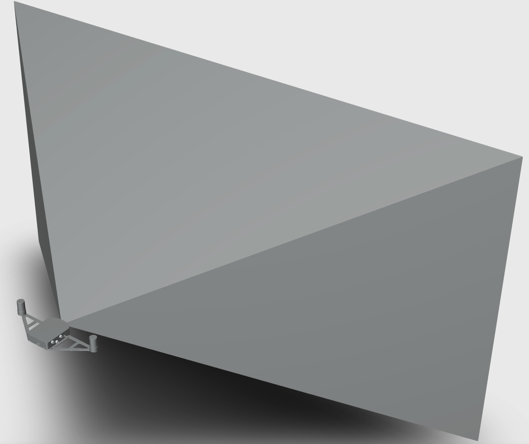
Power budget, compute requirement, mounting and calibration effort, ingress protection and temperature range, plus the ongoing cost of correction service subscriptions across a fleet. For a camera-based system, add two questions specific to the sensor: where the camera's field of view will actually point once mounted, and how much vibration the mount transmits. Vision-RTK 2 has a 100° horizontal and 64° vertical field of view, is IP66-rated and has passed salt spray and temperature shock testing; the documented caution is against mounting positions where high-frequency vibration deflects the housing by centimetres, which degrades visual feature tracking.
9. Commissioning, not just specification
Ask what the system needs in order to reach full performance for the first time. Any inertial fusion has to converge its biases, and that generally requires a period of good GNSS and varied motion — which is a commissioning procedure, not a datasheet line. If your robot is only ever going to operate in the difficult environment, find out where it is supposed to converge.
Questions worth asking a supplier
- What is the availability figure on a route with sustained obstruction, and how was it measured?
- What is the drift over a 30-second and a 120-second GNSS outage?
- Is heading available and accurate at zero speed?
- What does the position discontinuity look like at re-acquisition?
- How is the system calibrated, and does calibration have to be repeated after a mounting change?
- What does integration look like — days, or a quarter?
- What does the system need in order to converge for the first time, and where can that happen on my site?
- What is the correction-service cost per unit per year at fleet scale?
Where the technologies land
| Approach | Best fit | Watch out for |
|---|---|---|
| RTK GNSS only | Open sites: fields, large yards, rooftops | Availability collapses near structures and under canopy |
| RTK GNSS + INS | Mostly open routes with short, infrequent obstructions | Drift grows quadratically; heading needs motion |
| LiDAR SLAM | Structured, repeatable sites you control | Map building and maintenance; georeferencing; sensor cost |
| UWB / beacons | Fixed, bounded work areas | Infrastructure to install, survey and maintain |
| Vision + inertial + GNSS fusion | Unprepared outdoor environments with sustained obstruction | Lighting and scene texture; calibration quality matters |
How Fixposition fits
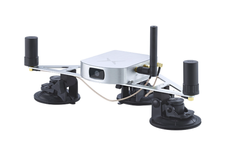
Vision-RTK 2 is a single integrated unit combining two multi-band RTK GNSS receivers, a camera, an IMU and optional wheel-speed input, fused by the xFusion engine into global position, orientation and velocity with covariances. PBx-A1 is the alternative for integrators who need to place the camera separately from the compute box, and supports mono and stereo external cameras. Open-source ROS 1 and ROS 2 drivers are available, and the starter kit ships fully configured and calibrated with two support calls with an application engineer.
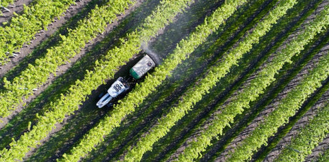
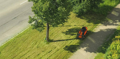
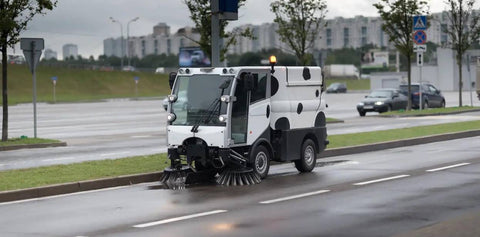
Fixposition states 100% availability in GNSS-denied or restricted areas and 10× superior performance compared with high-end RTK INS systems under typical GNSS-denied scenarios. The technology is deployed in agriculture, landscaping, utility robotics and geospatial applications, and was selected by Topcon for its next-generation RTK receivers.
Evaluate it on your own route. Get a starter kit, review the OEM integration path, or talk to an application engineer.


