











The most dangerous failure mode is the one that reports success
An RTK engine reporting fix while sitting in the wrong place has one of four causes: a false fix from incorrectly resolved integer ambiguities under multipath, a coordinate reference frame mismatch between base and rover, an antenna height or phase-centre entry error, or wrong base station coordinates. The last three produce a constant offset; the first produces an error that appears and disappears. Which of those you see tells you where to look.
Diagnose by the shape of the error
A constant offset, everywhere, always
If every point in your survey or every waypoint on your route is wrong by the same amount in the same direction, the problem is a reference or setup error, not a signal problem. In rough order of how often it happens:
- Datum and epoch mismatch. This is by far the most common cause of a solution that is confidently wrong by a roughly constant amount, and the mechanism is worth stating precisely: in RTK mode the receiver output is always in the geodetic datum used by your correction service. The receiver does not know that datum, does not validate it, and cannot warn you when it differs from the one your maps and boundaries use. Global and regional frames drift apart over time through plate motion, so the same physical point carries different coordinates in different frames and epochs. Note also that latitude, longitude and height are derived from the ECEF solution using WGS84 parameters regardless — so the LLH output can look ordinary while sitting on a different underlying frame.
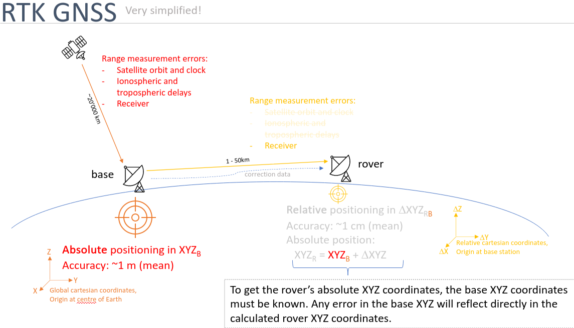
- Wrong base station coordinates. RTK positions the rover relative to the base, so the rover's absolute coordinates are the base's coordinates plus a measured baseline. Any error in the base coordinates reflects directly and invisibly into every rover position. A base set by averaging its own autonomous position is typically good to one or two metres after half an hour — against roughly ten centimetres or better if the same half hour is spent surveying it in against a correction service.
- Antenna height or reference point. Slant height entered as vertical height, phase centre confused with the antenna reference point, or the rover's mounting offset never measured. Vertical is usually wrong; horizontal can be too on a tilted mount.
- Antenna offset to the vehicle frame. The receiver reports where the antenna is. If your stack assumes that is the robot's control point, every position carries the lever arm as an offset — and it rotates as the robot turns.
An error that appears in particular places
If the position is correct in the open and wrong beside a building or under a structure, you are looking at a false fix. Reflected measurements were consistent enough for the engine to settle on a wrong integer solution, and it has no way to know. Signatures to look for in the logs:
- A position step at the moment the fix is re-acquired, rather than a gradual convergence
- A low ambiguity-resolution validation ratio at the point the fix was declared
- Disagreement between the GNSS solution and wheel odometry or inertial over the same interval
- Different results on repeated passes over the same ground
A diagnostic order that saves time
- Occupy a known control point. A surveyed mark, twice, in separate sessions. This separates a setup error from an environmental one in minutes.
- Confirm the reference frame end to end — correction service, receiver configuration, and whatever consumes the output. Write the frame and epoch down explicitly rather than assuming they match.
- Re-measure every physical offset from antenna reference point to vehicle control point, and check what your software believes those offsets are.
- Repeat the problem route and compare tracks. Repeatable error is systematic; scattered error is environmental.
- Cross-check against an independent sensor. This is the only method that catches a false fix as it happens, rather than afterwards.
Why cross-checking needs a different kind of sensor
A second GNSS receiver on the same robot shares the same sky and the same reflections, so it will often be wrong in the same way. Genuine independence means a sensor that measures something else entirely. A camera tracking the physical scene, combined with inertial measurements, produces a motion estimate that a reflected satellite signal cannot corrupt — and a fused estimator can therefore recognise that a GNSS measurement is inconsistent with everything else it knows, and downweight it.
This is the practical value of fusion beyond availability: it converts a silent failure into a detected one. Vision-RTK 2 carries covariance estimates in its odometry and position messages — position in m², orientation in rad², velocity in m²/s² — continuously updated from GNSS, IMU, visual features and wheel speed together. Your navigation stack therefore receives not just a pose but a statement of how much to trust it.
Frequently asked
Can a false fix survive for a long time?
Yes. In a stable reflecting environment an incorrect ambiguity set can persist for as long as the geometry holds, which is why time-based confidence heuristics do not catch it.
Should my robot trust the fix status flag?
Treat it as one input, not as ground truth. Consume the reported covariance, and cross-check against independent motion information wherever the application is safety-relevant.
Which reference frame should I use?
Whichever your maps, boundaries and downstream systems use. Since the output follows your correction service's datum, the choice is effectively made when you choose the service — so check it against your project requirements before you subscribe, and document the frame and epoch rather than assuming they match.
Know when not to trust the fix. Vision-RTK 2 reports position, orientation and velocity with covariances, fused from vision, inertial and GNSS. See the technology.


